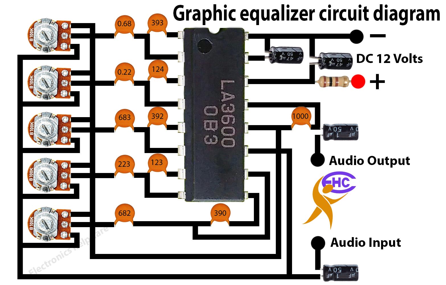
Graphic equalizer circuit diagram:
This is a 5 band audio equalizer. this circuit is used in an amplifier. normally any amplifier needs a pre-amplifier to control the sound quality. this circuit has audio input and audio output. here need 12 voltages to run this circuit. Graphic equalizer circuit diagram.

This is an amplifier circuit diagram. here used 2 transistors for one side. left side for 2 transistors. and 2 transistors for the right side. A1941 is a negative transistor PNP. and C5198 is a Positive transistor NPN. we also can use other transistors. same as these transistors. here all transistor Bases, collectors, and emitter are the same. we use here 12 voltage. we also can use a maximum of 24 voltage.
Thanks a lot for being with us. If you want another post then please visit our website. TDA7294
Build a Transformer or construct the transformer. Home Theater Circuit Diagram 5.1
Thanks a lot for being with us. If you want another post then please visit our website.
We have another post for you. like repairing, If you like electronics please visit our other post. electronicshelpcare.com
our Facebook page is Electronicshelpcare
Please like comment and share our post.
 Electronics Help Care electronics circuit diagram


