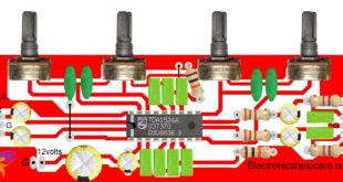
Sound booster pre-amplifier circuit diagram:
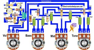
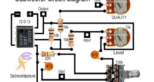
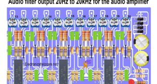
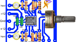
This is the Sound booster pre-amplifier circuit diagram. This board is for boosting the sound. This board works as a pre-amplifier. This circuit runs with 12-0-12 voltage to 15-0-15 voltage. Every amplifier needs this type of circuit. Normally, it’s included with the bass tone circuit. Sometimes we need more sound than we have to use this circuit.
It;s
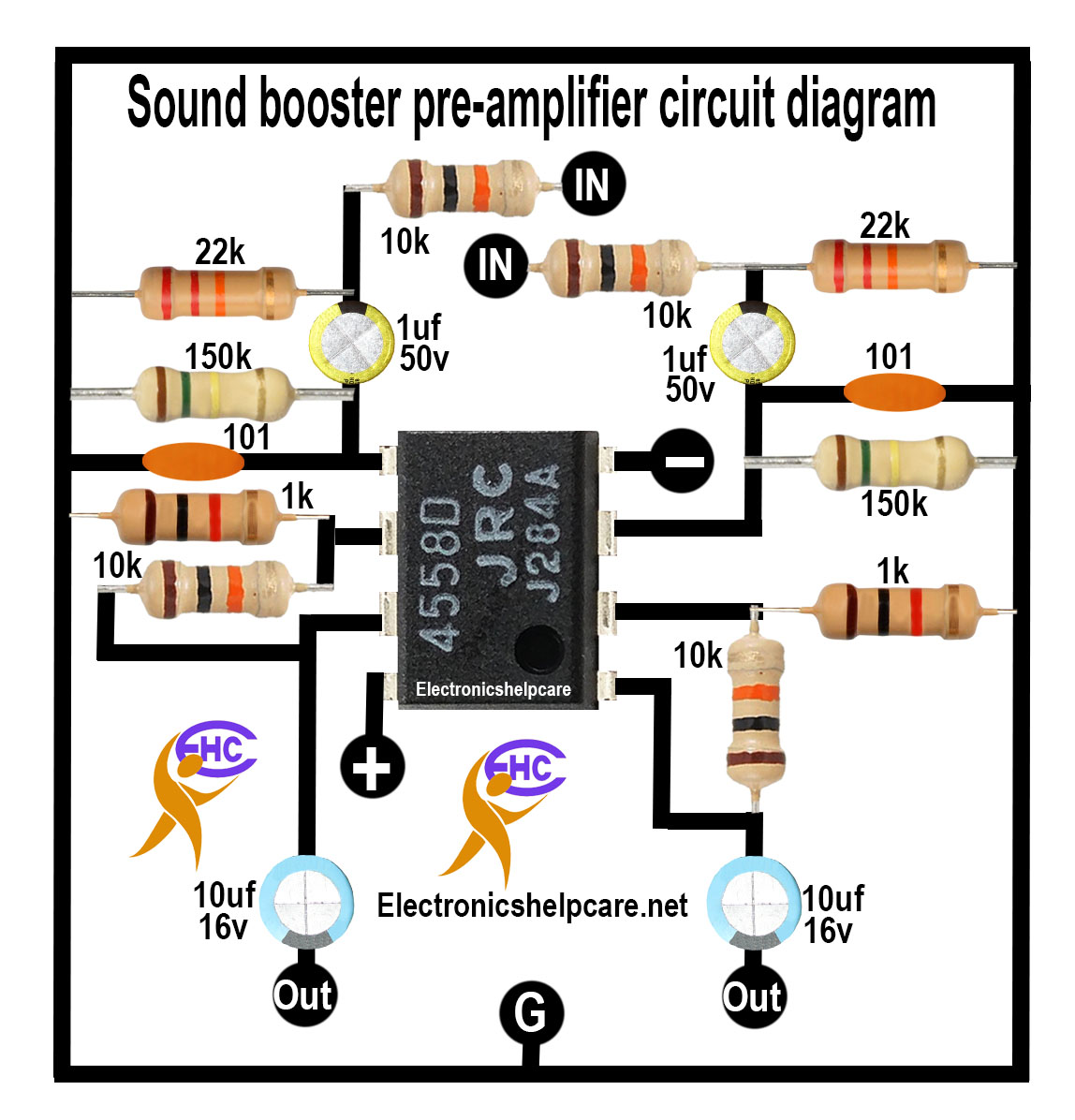
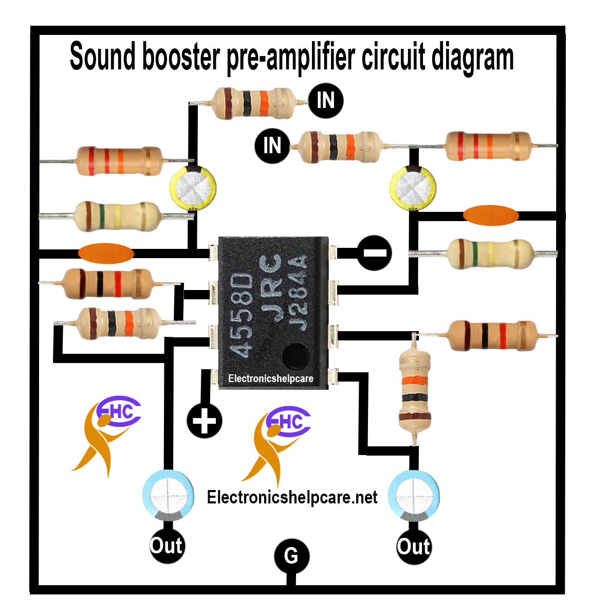
It’s a stereo circuit. This board must be used before the audio input. The voltage should be dual: positive, negative, and ground. The audio will connect with the input, and the amplifier input will connect with the audio outputs.
Audio amplifier 2X300W using LM4702:
This is an audio amplifier 2X300W using an LM4702 IC. The IC is also used with two pairs of transistors to make 300+300-watt outputs. We can use 50-0-50 voltage to 85-0-85 voltage, depending on the IC. We can see the voltage listed in the diagram. Here also need transistors. PNP and NPN transistors are needed in this circuit diagram.
the diagram
We have another post for you. like Amplifier circuit 200 watts
Transistor circuit for an amplifier
Build a Transformer or construct the transformer. Home Theater Circuit Diagram 5.1
Thanks a lot for being with us. If you want another post, please visit our website.
We have another post for you, like repairing amplifiers. If you like electronics, please visit our other post. electronicshelpcare.com
Our Facebook page is Electronicshelpcare
 Electronics Help Care electronics circuit diagram


