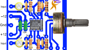
PCB LAYOUT MASTER STEREO PRE-AMPLIFIER: This is a PCB LAYOUT MASTER STEREO PRE-AMPLIFIER. Every amplifier needs this type of pre-amplifier to produce good sound. this circuit runs from 10-0-10 voltage to 18-0-18 voltage. it’s a stereo circuit diagram. Manufacturer = on semi The product Category is operational Amplifiers – Op …
Read More »DIY audio amplifier circuit
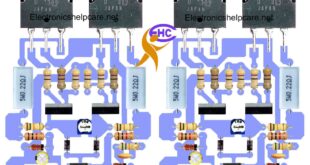
DIY audio amplifier circuit: This is a DIY audio amplifier circuit diagram. this is a mono diagram. This diagram can produce 150 watts using 2 transistors. 2sc5200 and 2sa1943 is a common transistor. We can also use another transistor in this circuit diagram. This diagram can produce strong watts because …
Read More »Audio amplifier circuit using tip41 and tip42
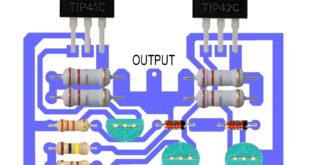
Audio amplifier circuit using tip41 and tip42: This is an audio amplifier circuit that uses tip41 and tip42. This circuit can produce 100 watts using these transistors. it’s a mono diagram. here use 25-0-25 voltage and 4 amperes. PNP and NPN transistors are used here so we can change the …
Read More »PCB Layout Power Amplifier
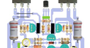
PCB Layout Power Amplifier: This is a PCB Layout Power Amplifier that uses BD249c and BD250c. it’s a mono-circuit diagram. here use positive negative and ground voltage. 50-0-50 voltage is used in this circuit. Bd249c is an NPN transistor. The material of the Transistor is Si. Polarity is NPN. Maximum …
Read More »Tone control circuit diagram using TDA1524A
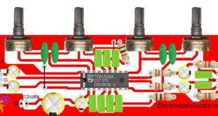
Tone control circuit diagram using TDA1524A: This is a tone control circuit diagram using TDA1524A. This is an audio equalizer Tone Control TDA1524A. This circuit diagram can control the Base mid and tone. This circuit needs 12 voltages. we can use 12 to 15 voltage. this is a mono-circuit diagram. …
Read More »Flip flop circuit diagram
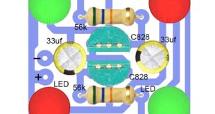
Flip-flop circuit diagram: This is a Flip-flop circuit diagram. flip-flop in a digital electronics circuit with two stable states that can be used to store binary data. The binary stored data can be changed by applying different inputs. Flip-flops are building blocks of digital electronics systems used in computers and …
Read More »Motor speed controller circuit
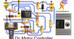
Motor speed controller circuit: This is a DC motor speed controller circuit diagram. This circuit diagram can control every single voltage DC motor, from 4.5 to 15 volts, using this NE555 IC. Here, we use the NE555 IC and a Z44n MOSFET, which is a negative-voltage MOSFET. negative voltage control …
Read More »AC to DC circuit diagram for transistor amplifier
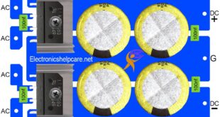
AC to DC circuit diagram for transistor amplifier: This is the AC to DC circuit diagram for the transistor amplifier. Every amplifier needs this board to make the voltage. A good amplifier needs a good voltage. Normally, we need dual voltage for the amplifier. In this circuit, we can make …
Read More »dc power supply for power amplifier
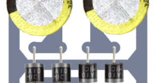
DC power supply for power amplifier: This is a DC power supply for the power amplifier. we need this type of diagram for any amplifier. it’s the dual power DC voltage diagram. positive negative and the ground voltage. here a bridge diode is to make AC to dc voltage. we …
Read More »Bass circuit diagram for amplifier
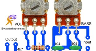
Bass circuit diagram for amplifier: This is a Bass circuit diagram for the amplifier. every amplifier needs a bass tone control circuit. here this circuit can control the bass. this board used 2 adjustable volumes. One is for vol and another is for Bass control. here, there is no need …
Read More » Electronics Help Care electronics circuit diagram

