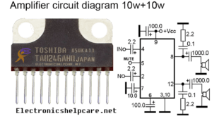
Transistor amplifier using A1941 and C5198:
This is an Amplifier circuit diagram using transistors. It’s an NPN and PNP amplifier. here used c5198 and a1941 transistors. this is a paired transistor. one pair transistor can make 80 watts. that means this c5198 and a1941. c5198 is a positive transistor NPN. and a1941 is a negative transistor PNP. in this circuit we can use a maximum 35-0-35 voltage and 3 amperes. but we are using 25-0-25 voltage and 3 amperes.

driver transistors, A940 and C2073 are used in this circuit diagram. A940 is a PNP transistor and C2073 is an NPN transistor. all transistors Base Collector and Emitter are the same. 1st is Base 2nd is Collector and 3rd is Emitter. we also can use another transistor following the PNP/NPN and BCE. Here Maximum resistor is 1 watt. 3 watts for sound output. and 2 watts for passing the voltage. All capacitors will be a minimum of 50 voltages.
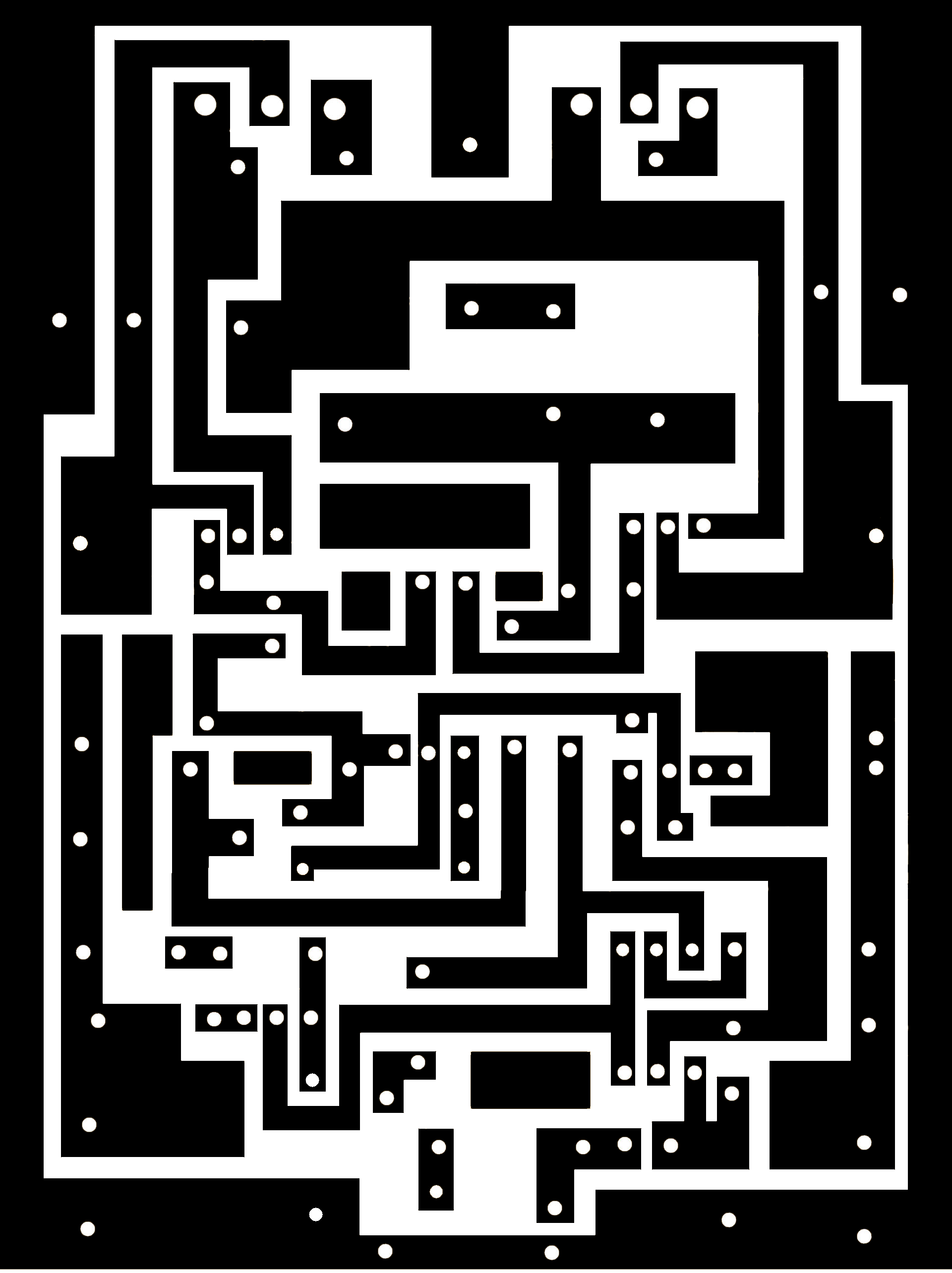
please always use a good quality transformer. good quality diode and good quality capacitors. the voltage capacitor needs 50 voltage and 10000 mfd. we know that Voltage X amperes= watts. so always use a good voltage to get good watts. the main transistor are will be of good quality of transistors. in the market, we can get much quality of transistors. please always try to use good-quality of transistors.
On our website, you can get many important circuit diagrams. not only amplifier but also inverter. voltage controller. transistor amplifier. STK amplifier. Class-D amplifier. bass circuit/ low pass filter
Please always stay with us to get circuit diagrams. and give us advice at Electronics help care
 Electronics Help Care electronics circuit diagram
